
|
||||||
|---|---|---|---|---|---|---|
| Echocardiography 5 minutes before starting
|
||||||
Echocardiographic examinations |
||||||
|
—Echocardiographic examinations |
—Cardiac function and PA pressure |
—Examples of pathological |
||||
| Transthoracic examination | ||||||
|
Guidelines and Standards Guidelines for Performing a Comprehensive Transthoracic Echocardiographic Examination in Adults, 2019 Recommendations for Cardiac ChamberQuantification by Echocardiography in Adults, 2015 Two-dimensional views |
||||||
|
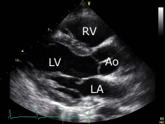
Parasternal long axis: place the transducer approximately on the 3rd intercostal space left parasternal. The transducer's index mark is directed towards the patient's right shoulder. The right (RV) and the left ventricle (LV), as well as the aortic bulb (Ao) and the left atrium (LA) can be displayed. |
|||||
|
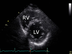
Parasternal short axis (apical level): turn the transducer 90° clockwise from the previous position and tilt it a little bit upwards and to the left. Sometimes is will be necessary to place it one intercostal space deeper. The apex of the left (LV) and right (RV) ventricles can be displayed. |
|||||
|
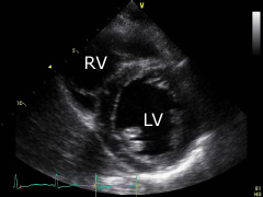
Parasternal short axis (papil- lary muscle level): from the former position tilt the transducer some downwards and to the right. The left ventricle (LV) at the level of the papillary muscles and the right ventricle (RV) can be displayed. |
|||||
|
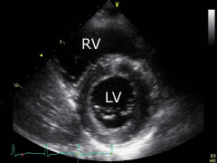
Parasternal short axis (mitral valve level): further tilt the transducer a little from the same position down to the right. A cross section of the left ventricle (LV) at the level of the mitral valve and the right ventricle (RV) can be displayed. |
|||||
|
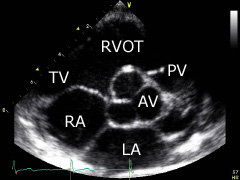
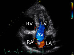
Parasternal short axis (aortic valve level): tilt transducer a little more from the same position down to the right. The aortic valve (AV), the pulmonary valve (PV), the left atrium (LA) and the right atrium (RA), as well as the tricuspid valve (TV) and the right ventricular outflow track (RVOT) can be displayed. |
|||||
|
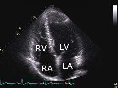
Apical four-chamber view: place transducer on the 5th intercostal space, aprox. left midclavicular. The transducer's index mark is directed towards the patient's left side. The left (LV) and the right ventricle (RV), as well as the left (LA) and the right atrium (RA) can be displayed. |
|||||
|
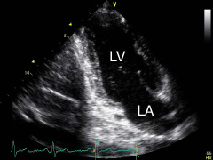
Apical two-chamber view: turn the transducer aprox. 60° counterclockwise from the previous position. The left ventricle (LV) and the left atrium (LA) can be displayed. |
|||||
|
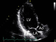
Apical three-chamber view: turn the transducer further, aprox. 60° counterclockwise from the previous position and side tilt slightly. The left ventricle (LV), the left atrium (LA) and the aortic bulb (Ao) can be displayed. |
|||||
|
Apical five-chamber view: show a four-chamber view and then tilt the transducer slightly down. The aortic valve (AV) can be seen in the middle, between chambers. Tilting the transducer to the opposite direction, the coronary sinus can be displayed. |
|||||
|
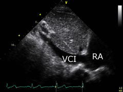
Subcostal view: place the transducer on the subxyphoid region. The transducer's index mark is directed towards the patient's head. The inferior vena cava (VCI) can be displayed. Turn the transducer clockwise slightly to diplay the right and left ventricle, as well as the right (RA) and left atrium. |
|||||
|
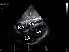
Subcostal four-chamber view: turn the transducer aprox. 45° clockwise from the previous po- sition and tilt some. The liver (L), apex of the left (LV) and right (RV) ventricles, as well as the left (LA) and right (RA) atrium can be displayed. |
|||||
|
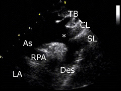
Suprasternal view: place the transducer on the suprasternal region. The transducer's index mark is directed towards the patient's head and turned aprox. 45° to the right. The aortic arch (*), the neck arteries (TB, CL, SL) and the right pulmonary artery (RPA) as well as the left atrium (LA) can be displayed. |
|||||
| Measurements and normal values | ||||||
|
|
||||||
The American Society of Echocardiography has published recommendations
for chamber quantification. This document can be downloaded directly from
the ASE:
ASE Chamber Quantification Update, 2015. |
||||||
©
Derliz Mereles |
||||||
|
echobasics | free echocardiography tutorial online since 2004 |
||||||
 ORC
ORC